Garrattfan's Modelrailroading Pages
OO9 NGG16
Chapter 04 Valve gear Installation, Truck 1
December 26, 2008 till April 15, 2009 After finishing one truck as far as wheel and flycrank installation, and at the same time not having resolved the problem of too tight gearing in the second gearbox, I pushed ahead with the valve gear installation on the one truck that worked. Setting eye on the valve gear is impressive, to say the least due the amount of parts involved. Many modelers consider assembling the valve gear as the most daunting task of a steam loco and not without reason. Every gear halve consists of nine main parts and seven links. Including the contact with the cylinder and the slide bar there are eighteen places where a valve gear can fail. If every part has a success rate of 99,5%, in other words it hampers every 200 revs, the total success factor of the gear halve will be 0,995 to the power of eighteen. Given that a Garratt has four gears in all this will be 0,995 to the power of (18*4) = 69,7 %. Well, I can tell you 99,5% per parts looks like a whole lot, but the end result is an engine that will run miserably. So when assembling the valve gears take accept nothing less than perfection!! To reassure you: it can be done, many modeler have, beating the maths above with logic, accuracy and perseverance.
|
These are the names of the parts of the Walschaerts valve gear. Learn more about the Walschaerts valve gear on Steam4me |

The complete gear set for one truck laid out. It seems a little tedious job to lay them out just for the sake of a photo, but it is an excellent way to acquaintance yourself with the gear. It is important to know the construction. Unfortunately Iain Rice's comments on most kit's valve gear is all too true: "You'll almost certainly find the radius rod and lifting links etched as one piece, in a straight line (engine mid-gear)". Yes sir, bulls eye!! For those who do not get the point: in mid-gear a locomotive would not move. A better choice would be to depict the model in forward gear (radius rod in the lower part of the die block). Admittedly wrong if the engine is moving backward, it would be correct in most cases. The radius rod itself would be moving as well and this would give you a better appreciation of the complex movement of the Walschaerts' valve gear. I'm afraid I'm too inexperienced a modeler to change that. May be later when I grow up.....
|
A detail view of the left side gear set. "Left" is relative to the truck. If this would be the gear of the rear truck, it would be the right hand gear (sigh :-o )
|

Remove the cusped sides of each part. It is a tedious job but the parts of the valve gear will look so much better. At the left an untreated radius link, right a treated one. Be prepared to spend one and a half hours on it (for each truck that is.....)
|
The connecting rods, cleaned from etch burrs and boss soldered to the backside (4.4; 31-12-2008) |
The connecting rod and crosshead upside down. The paper prevents flux and solder to trickle down and make the whole thing solid. It needs some getting used to, but once you get the hang of it, it is a more reliable and controllable method than old fashioned try and hit riveting (4.5; 31-12- 2008)
|
Aaaaahhhhh, ooooohhhhhh |
And so forth, union link and combination lever added (4.5; 31-12-2008) |
Valve gear brackets carrying the valve gear and the slide bars. Excellently designed by Backwoods (4.6; 31-12-2008) |
Trying to hook it all up at once. The next day I struggled during the better part of the morning assembling the radius link on the radius rod and the bracket. Four layers of nickel silver, a rivet and a sheet of paper, all within a few square mm's. First it took me quite some time to figure out in which order the layers had to be arranged. As it turns out there is a small error in the drawing in chapter 4. It suggests that one of the radius link halves should be outside the bracket. That is wrong. Both radius link halves should be inside the bracket with the radius link in between. The text of the manual describes it correctly. Another problem is the length of the rivets. A rivets is simply not long enough to pierce completely through four layers. When I finally found a way to keep all things together and tried to solder the contraption other links came apart. I needed a deep breath. After an hour's rest I decided to leave out one radius link halve leaving the outer halve to represent the whole thing. Who is going to see that anyway. Taking a close look at prototype photos I found that the double link isn't prototypical anyway. So my tip is: don't try it, just leave out the inward radius link (4.9-4.10 ; 01-01-2009)
|
Ten minutes later I had everything soldered together (4.10; 01-01-2009) |
And another half hour later the first halve of the valve gear was assembled (4.11; 01-01-2009) |
Just for fun I trial fitted the half finished valve gear to a truck. Wooooow!! |
Don't be fooled, a lot of work remains, but it slowly beginning to look like a steam locomotive. |
End of New Years Day 2009: one valve gear completed (4.11; 01-01-2009) The valve gear assembly consists of 34 parts with 14 soldered but moving joints and weighs.......2 grams!! |
After the steady progress came the disappointment. The truck that I fitted with the complete valve gear assy as per instruction 4.21 just wouldn't move. Happily I started tuning and tweaking and although I did progress somewhat, I just couldn't persuade the truck to run without binding "rock solid" two or three times per rev. As the crossheads kept falling off the slide bars I could hardly determine the cause. Keeping an eye on two sets of valve gear, keeping two crossheads on the slide bars at the same time and keep the whole thing running as well is simply too complicated a task for a single focused man mind like I am. After a few days it got on my nerves. To distract myself from the problem I worked on the boiler assy for a while. In the meantime I sought contact with other builders (http://www.rmweb.co.uk/ is a good source) and published photo's on the problem. First thing was to establish whether I had done things right or whether I had made some kind of fault. As it turned out the whole assy seemed to have been built quite decently. I got two tips (thanks Ben!) 1. Cut the cylinder assy in two and spread the halves by about 1 to 1,5 mm. This will provide extra clearance. 2. Make some kind of provision on the back of the crossheads to prevent them from falling off the slide bar I decided to do the second suggestion first. Cutting the cylinder assy in two is rather radical and I preferred to try some reversible actions first. By this time April was well underway. |
To keep the crosshead on the slide bar I wanted to solder a 0,3mm steel wire on the back. I filed a slit |
And soldered the wire and cut it off. On doing so the left connecting rod got loose and fell off. So in the end I could only test the right gear set.
|
And guess what: the right side crosshead now runs flawlessly!!! The bad news is that the left crosshead is still stuck rock solid
|
A back side view on the right crosshead |
| Encouraged by the success on the right side I continued thinking about and looking at the left side. I looked closely at the cylinder and saw it was slightly out of line in relation to the piston rod. I knew tolerances in the cylinder were tight so I guessed this could be a cause. In a hunch I gave the cylinder a twist. The left crosshead came loose and fell all the way into the cylinder. Success at last!!!
It moved a little coarse so I decided to resort to a proven method of mine to make moving parts slide easier: polish them!! |
Polishing the slide bars. I took an ear swab, put it in my Proxxon, put some polishing paste on it and polished the slide bars and the piston rods of both sides in every angle. The polishing erases any left over burrs and irregularities and gives the brass a smooth surface.
|
The result after e few minutes of polishing, as shiny as shiny can be. Look at the piston rod, the room mirrors in it. Note that the sharp edges of the slide bar has become rounded, giving an easier ride for the crosshead.
|
Whoohahahahaaaa! Unfortunately I had to put this beauty in the claws of a beast and torture it with a soldering iron. Sorry I got carried away. I should have dryly commented: I soldered the left connecting rod back into place. |
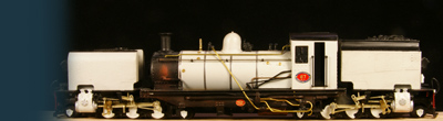
Next I patiently fiddled the whole valve gear assy into place. Believe me it is not easy to maneuver six independently moving rods into six tiny holes. But when I did......it ran, the very first time. No doubt about it. This truck runs!! The irregular movement in the film is caused by my unsteady hand and the poor quality of the vid option of my camera rather than by the mechanism. There is a whole lot of work remaining: the bushes of the connecting rods must be soldered to the cranks, the return cranks must be fastened, the electric pickup must be done etc. etc. But the solution is there!! It has been twelve weeks after I ran into the problem..... take your time. Only days later I had the whole valve gear installed |

Still some work left on this photo |
| The final result in motion |


Sign my
GuestBook