Garrattfan's Modelrailroading Pages
OO9 NGG16
Chapter 03 Wheel and Flycrank installation
December 24, 2008 till ....
After finishing the gearbox assembly of one truck I couldn't wait and finish the other truck first. I just wanted to push on and set out for the wheel and flycrank installation. First important thing to realize is that the drawing for this chapter can be found in chapter 4. Take a good look or else you won't be able to understand some remarks. Second I came to realize that absolute accuracy in this chapter is paramount. Read Iain Rice's "Locomotive kit Chassis Construction" and you'll know. Sloppy work will give sloppy performance.
When I carefully read the instructions in chapter 3 there was mention of 14BA threading. I tried locate them in the Netherlands but was unable to get them. I wonder why such internationally sold kits are designed with such typically English measures. I mailed with Peter McParlin about two alternatives:
- buy a M1 tap, tap the the hole M1 and then insert the screw
- ream the hole to 1 mm, insert the screw and solder the thing solid with 180C solder
Peter advised me the latter. So I followed that road
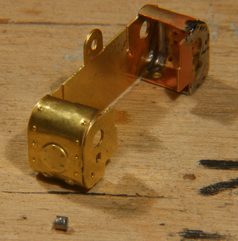
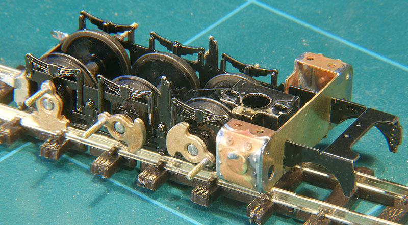
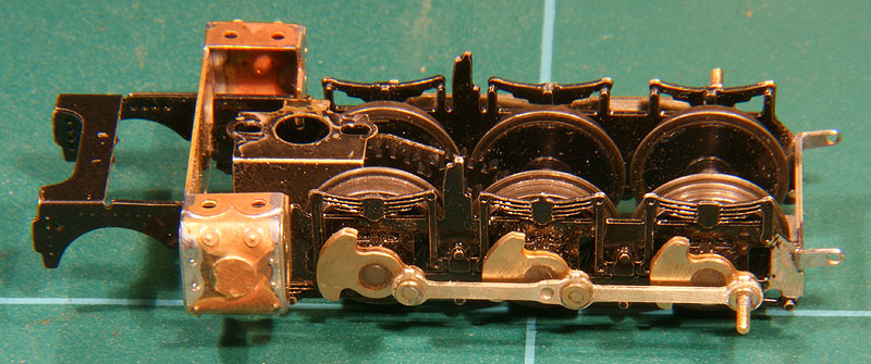
Getting the frame plates correctly positioned needs the cylinder assembly in place (3.2) |
I annealed the cylinder sides before bending them. Annealing, softening the metal, makes it less springy. Be careful though, brass once softened cannot regain its strength like steel by dipping it hot into cold water, so don't overdo it. The cylinder assembly was simply slotted in, but not fixed. The running plate was clipped on and the rear cross member was soldered into place (3.3) Note that I have already painted the chassis. With the outside frame closed by the cross member I wouldn't be able to reach the sides between the frame plates anymore. The outside of the frame are a lesser problem so any wear and tear of the paint during further handling won't matter too much.
|
Drilling to 0,9 mm, a little reaming, soldering and filing flush against the crank. Twelve times if you please (3.5) |
Next the flycrank axle holes were reamed to fit the axles. This is a delicate job. I wanted them to fit very, very tight, just enough to press fit on the axle but unable to slide by itself. This requires a tolerance of no more than a few 0,01 mm. (3.6).
|
Cranks in place. Contrary to the instructions I glued the flycranks with two component epoxy, allowing me to adjust the flycranks a little before the glue sets. Seeing the flycranks move in sync with the coupling rod temporarily fitted on, made my heart skip a beat. Yes, this is why I like outside framed loco's.
|
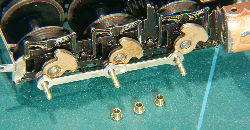
To good kit building practice, the etch plates have holes that are a little undersized. They must be reamed a little to make the bushes fit. Again a tight fit is paramount, but this time the bushed should be able to revolve freely, as opposed to the flycrank where I strived to have a press fit. The difference lays in just a few twists of the reamer... Try fit every few turns. Work carefully and slowly. The coupling rod is functional in the drive of the loco, the less play you have the better it'll work (3.9) |
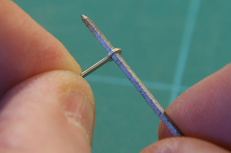
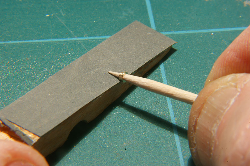
Mark your reamer to speed up work Once the reamer had done its work a black mark was made on it, so all consecutive holes could be reamed easily to the same size!! In my case the fit was so exact that the rod revolved completely free around the bush yet would only allow the bush and the tooth pick to change the 90 degree angle just a little (3.9)
|
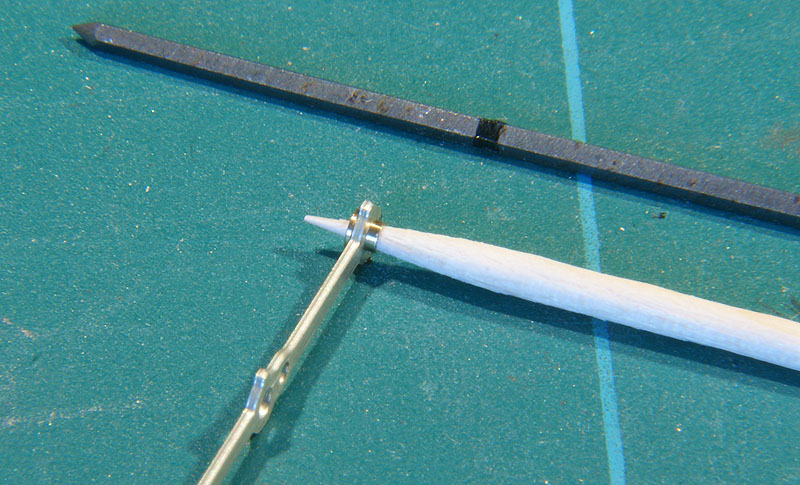
Removing burrs on the filed bushes is easily done with a tooth pick. |
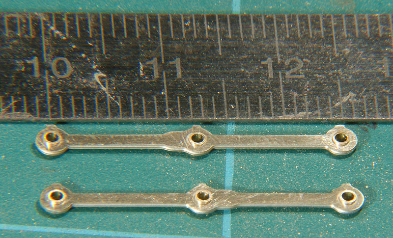
Complete coupling rods and correctly sized bushes, only protruding about 0,2 mm (3.9) |
All three flycrank mounted and the coupling rod in place with bushes soldered. The first time I soldered a bush the whole thing filled solid. I figured that solder would not go where grease is so I dabbed the surface not to be soldered with vaseline. With the low melt solder I used (70 C) it worked fine. Note that the axle holes in the flycranks have been filled. I used the same epoxy that I used to glue the cranks and filed it flush after setting (3.10)
|
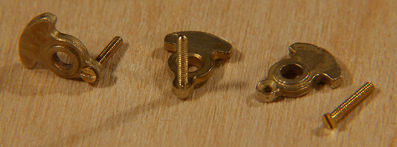
The left side during quartering. The first crank had been installed and quartered the day before and was already rigidly fixed to the axle. the other two cranks where reamed a little more than tight fit (NO MORE than two or three turns with the reamer, one turn at a time and then fit after each turn). They had no play but could move over the axle with some pressure. They were put on with epoxy glue. I used unfiled (i.e. longer) bushes turned the wrong way to fit the coupling rods and than pushed the assembly back and forth a few times on rails. The two freshly fitted cranks adjusted themselves in the quartered postion without a problem (3.11 - 3.12).
|
The unit is left to cure. After curing the coupling rod and the bushes are taken off and the rims of the axle holes are filled with epoxy and after curing filed and sanded flush against the flycranks. I put the coupling rod in place with the filed bushes in the correct position and soldered them. I clipped off the protruding pins on the first two axles and filed them flush. NOT the third, this one will be needed for the returncrank to fit. |
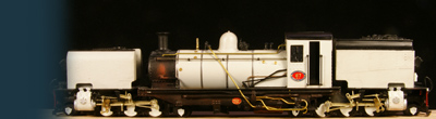
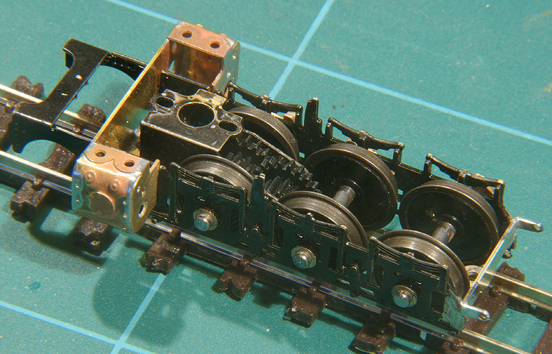
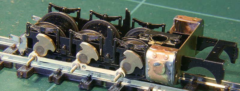
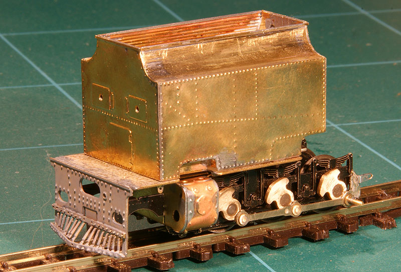
The rear unit after chapter three (with some advance work on the superstructure when I had time because of the worm gear problem). |
In the mean time I tried to get the second gearbox working. It just wouldn't run. The gears seemed to mesh correctly, I could find no fault in the bushes, every single gear worked fine, but as soon as I assembled the gearbox it ran stiffly. No trace of binding, it ran very evenly but stiffly. I consulted Backwoods once more and Pete suggested some glue could have creeped in the idler. I reemed it a little (very, very little) and it ran. The gearbox worked superbly. From than on I could continue working ont the second truck.
|
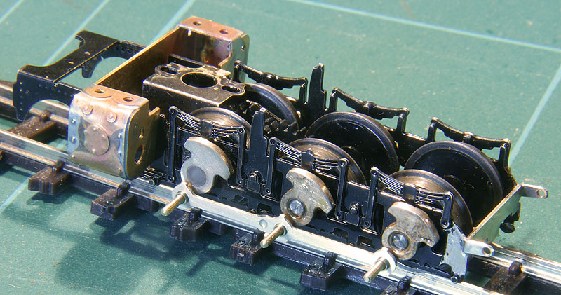
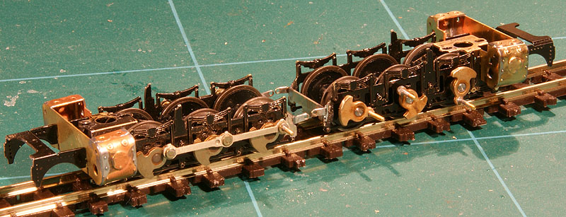
The second truck in the phase of flycrank installation |

Sign my
GuestBook