Garrattfan's Modelrailroading Pages
AD60
1.1 Chassis drive units
|
Instructions [1] to [21], page 7 of the rewritten instruction manual |
|
After the inventory fun I started the kit in all earnest |
|
 |
[1]
I cut the frames from their etches with a jeweller's saw because the bridges are too thick to cut with a knife and the gaps between the frame and the fret too narrow to use flush cut pliers. Be extremely cautious not to bend the frames while sawing. Once bent you'll have a hard time getting it perfectly straight again. If you might happen to bend it, lay it on a glass plate. I have a sheet of hardened glass shelf from a disposed refrigerator. Works fine. Put the frame on it and push on the corners and see where it jumps up. Bend a little bit and test again etc. until the frame lies dead flat on the glass. By the way, the frames are 0.84 mm thick
On the frets the difference between the right and left frame is obvious. Once separated it can bee seen from the counter sunk holes (white arrow) provided for the spacer screws (161)The countersunk side is always on the outside. |
Two down, two more to go. |
|
 |
Next thing to do is file all the etch cusps away. You will not find this in the instructions. I know it is a tedious job but I deem it is necessary.
Just do the job. Every frame takes about 30 to 45 minutes to be done but it is well worth it. Switch on the radio and enjoy the music, forget about time. Work your way carefully around the frame. DO NOT file the holes for the axles however. They will be reamed.
The cusp issue makes the difference between an etched and a milled frame painfully clear: an etched frame may contain intricate detail but is way more laborious. A milled frame would have smooth edges and would be more accurate (etching is a relatively inaccurate process) so it is ready to use. |
Look at the difference. |
|
Small slits where you file can't go can be treated with a sanding disk from you Proxxon / Dremel tool |
Yep, tedious and boring work. |
 |
Two frames done and two to go. I first turned my attention to completing one frame set rather than de-cusping all four frames (yes, I got fed up and impatient, happens to everybody). All parts for both units come from the same bags. If you open the bag you have all parts for both unit lying around on your work desk. It is a good idea to temporarily store the parts you will not use for the first unit in a box. |

The lines on the cutting mat will help you to keep the reamer perpendicular to the frame. |
Instructions [2-3] The process is easy. Find yourself a suitable sized reamer, a five edged tapered piece of steel. Slowly turn this reamer in the holes. The edges will cut the brass away a little on every turn. The taper will drag the reamer further into the hole. Ream a little at a time, then trial fit the bush, ream more etc., until the bush press fits ever so tight in the frame. The first bush is the most critical: you don't know how far the reamer needs to go. Take your time and establish that point carefully, one twist at a time. Once you've found how far to ream make a marking on the reamer with a fine pointed waterproof marker. The next holes can subsequently be reamed quickly until close to that marker, only the last bit will need close attention.
|
If you work well there is not even a slightest hint of a gap between bush collar and frame. |
|
 |
|
Press fit means: having the tolerances so tight that you can fit the bushes by sliding them in the holes and yet the bushes not falling out when you turn the frame upside down. Q.E.D.!! |
|
After [4-5] |
|
 |
[6-9] Getting parts out of an etch seems straightforward. For this particular kit I would recommend using a sharp hobby knife rather than a flush cutter because the spaces between the fret an the part are really tight. It is next to impossible to get between. I us a 3 mm thick pieces of aluminium sheet as a solid underground. Do not cut on your cutting mat as this will inevitably deform your etched parts. |
 |
The pilot plate (no 164) in the process of de-cusping. |
 |
The filed and de-cusped pilot plate. Isn't it sheer beauty? The scratch marks come from grain 800 emery paper. I have a sheet of it laying flat on my work area. After filing the cusps I run the part dead flat over the emery paper which removes all rough edges that result from the filing process. It also offers the advantage that it roughens the brass surface for later painting. The scratch marks are so tiny that they won't show after painting. |
Assembling the unit frames needs a certain order to make things easy. First you screw the two frame plates together with the two turned brass frame spacers, one of which can be seen on the far left. Screw the spacer screws tight on one side. On the other side screw until just tight and then loosen the screws two turns back to make room between the frame plate. Fit the a pickup mounting plate (no 163) on the rear side, take the frame between your fingers to prevent it from falling out again. Push the frames apart on the top side and slide the rear chassis mounting plate (no 168) in it slots. Press the frames together and tighten the rear spacer screw just so much as to allow a little bit of movement. |
|
 |
Next, slide the front pickup mounting plate (no 163) in place, again hold the chassis between your fingers there to prevent it from falling out again, push the frames gently apart on the top side to slide the motor mounting plate (no 162) in its slots and tighten the front spacer screw. Turn it a half turn back to allow movement of the frame plates at the front. Now skew fit the pilot plate (no 164) between the frame plates as shown on the photo. If the space is too tight do not force, but release the front spacer screw just enough to let the pilot plate pass between the frames. Finally put the chassis on a glass plate (or any other positively flat underground) and tighten both spacer screws. |
 |
[10-14] |
Before fitting the axles in the chassis run a reamer through the axle bushes ever so lightly to remove the burs of the turning process (as per [20]). The bushes' fit is so tight that these burs will impede performance. Take care not to ream the bushes themselves accidentally. |
|
First chassis after [15-18], though not soldered yet, the second chassis is underway |
|
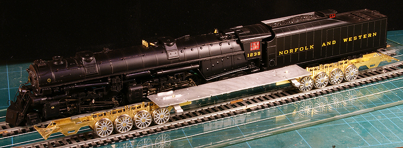
After screwing together the second chassis the first opportunity came to fit the boiler cradle footplate and the loco in its full length for the first time!! |
|
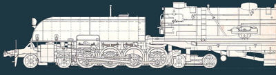
AD60 chassis in comparison to the glorious N&W A-class |
|
Whatever you do, do not overheat the frame to prevent warping |
[14 and 13] Soldering the frames is not difficult but has a few points of attention.
|
I skipped the [19] and [21]. I did ream the gears to fit on the wheels as per [20]. At this stage I will do nothing this makes disassembly impossible and fitting the main gear on the driving is one of those things. Why? Because I need to paint the locomotive and to do that I will largely disassemble the chassis again. |
|


Sign my
GuestBook